
PCB assembly services for CCTV camera manufacturers: A complete guide
 Utsav
•
Sep 11, 2026
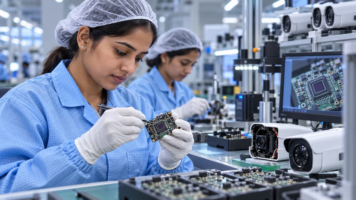
CCTV cameras rely on precisely assembled electronic circuits to process images, manage power, handle communication, and store video data. At the center of all this is the printed circuit board assembly (PCBA), the component that ties everything together and allows the camera to function correctly.
For manufacturers, choosing the right PCB assembly partner directly affects product quality, production volume, testing outcomes, and total manufacturing cost.
This guide covers how PCB assembly works for CCTV cameras, what to look for in a supplier, and what to watch out for during production.
Table of Contents
What Is PCB Assembly for CCTV Cameras?
PCB assembly is the process of mounting electronic components onto a bare printed circuit board to create a working circuit board assembly (PCBA).
A single CCTV camera can contain multiple boards depending on the design. Common boards include the main processing board, image sensor board, power supply board, network communication board, IR LED control board, motor control board, storage interface board, audio circuit board, and wireless communication board.
The exact configuration depends on the camera type and feature set. An IP camera needs circuits for Ethernet communication, image processing, and power management. A PTZ camera needs all of that plus motor-control electronics for pan, tilt, and zoom functions.
Why PCB Assembly Quality Matters
CCTV cameras run continuously, often in demanding environments. A defect in the PCBA, whether a poor solder joint, a misplaced component, or an inadequate power circuit, can cause problems like unstable video output, communication failures, overheating, or complete product failure.
A controlled assembly process helps manufacturers maintain consistent quality across production runs. It also reduces manual assembly work, improves component placement accuracy, and allows boards to be tested before they are installed in the finished camera. For manufacturers scaling up production, a reliable assembly process is what makes that growth possible without introducing new defects.
Components Used in CCTV Camera PCBAs
CCTV camera circuit boards contain a range of electronic components. The specific parts depend on the camera design, but several categories appear in almost every build.
The image sensor converts incoming light into an electrical signal. Most modern security cameras use CMOS image sensors, which can be mounted directly on the main board or connected through a separate module.
The system-on-chip (SoC) handles image processing, video encoding, network functions, and other operations. The specific chip depends on the camera architecture and required features.
Security cameras use several types of memory for firmware storage, temporary processing, and logging. Common options include DRAM, NAND flash, NOR flash, and EEPROM.
Power management circuits regulate the incoming voltage and distribute the correct power levels to different parts of the camera. Components in this section include voltage regulators, DC-DC converters, MOSFETs, diodes, inductors, and capacitors. Unstable power supply is a common root cause of camera failures, which makes this section of the board particularly important to design and assemble correctly.
IP cameras require components for Ethernet, Wi-Fi, or other communication protocols, typically including an Ethernet PHY, RF modules, and associated connectors.
Most security cameras include infrared LEDs for night vision. The PCB assembly for this section includes LED drivers, current-control circuits, and connectors.
PCB Assembly Technologies
PCB assembly manufacturers use different technologies depending on the board design. CCTV cameras commonly use one or more of the following.
Surface mount technology (SMT) places components directly onto the surface of the PCB using automated pick-and-place machines. It supports compact, high-density boards and works well at production scale. A standard SMT process runs from solder paste printing through paste inspection, component placement, reflow soldering, and automated optical inspection.
Through-hole technology (THT) mounts components through holes drilled in the PCB. Some components, particularly connectors and parts that need extra mechanical strength, are better suited to through-hole assembly. Wave soldering, selective soldering, or controlled manual soldering may be used depending on the board.
Many CCTV boards use both SMT and through-hole components. A capable assembly partner should handle both processes on the same board without treating one as secondary to the other.
The PCB Assembly Process
A professional assembly process follows several controlled stages. Understanding each stage helps manufacturers ask better questions and catch problems earlier.
Before production starts, the assembler reviews all manufacturing documentation including Gerber files, bill of materials, pick-and-place files, assembly drawings, and PCB specifications. A design-for-manufacturing (DFM) review at this stage can catch potential production issues before they become costly problems in the factory.
Component sourcing comes next. The assembler obtains parts according to the approved BOM. For CCTV boards, which can contain dozens of different parts from multiple suppliers, a controlled procurement process matters. The supplier should manage component specifications, approved manufacturers, lead times, and counterfeit risk.
For SMT assembly, solder paste is applied to the PCB through a stencil. The volume and position of the paste directly affect solder joint quality. Modern production lines typically run solder paste inspection (SPI) to verify the paste before placement begins.
Automated pick-and-place machines then position components on the board using the assembly data. Accurate placement is especially important for fine-pitch packages, BGA components, and densely populated boards.
The board passes through a reflow oven following a controlled temperature profile. The solder paste melts and forms joints between the components and the PCB pads. The thermal profile is selected based on the solder material, PCB design, and component requirements.
Automated optical inspection uses cameras to check the assembled board for common defects including missing components, incorrect components, placement errors, and polarity issues. AOI is an important checkpoint but does not replace other forms of testing.
X-ray inspection is used for solder joints that are not visible from the surface, particularly under BGA packages and similar hidden connections. IPC-A-610 provides acceptance criteria for these inspections.
If the board includes through-hole components, these are assembled and soldered after the SMT process using the appropriate method for the board design.
Some camera boards require firmware to be loaded during manufacturing. This can happen before final assembly or during a dedicated test stage, depending on the product architecture.
Functional testing is the final stage. The assembled board is powered up and verified against defined performance criteria. For a CCTV PCBA, this typically includes checks for power levels, network communication, image signal processing, sensor interfaces, IR control, and storage functionality.
Quality Standards
Two IPC standards are widely used in PCB assembly. IPC J-STD-001 defines requirements for soldered electrical and electronic assemblies, covering materials, processes, and soldering requirements. IPC-A-610 defines acceptance criteria for electronic assemblies, including visual inspection standards for solder joints. Both standards received revision J updates in 2024 and are commonly used together on the same production line.
Manufacturers should specify the applicable IPC class in their documentation. The correct class depends on the product type and end-use environment and should not be assumed by the assembler.
Regulatory and Compliance Considerations
CCTV cameras sold in the European Union and several other markets must comply with the RoHS Directive (2011/65/EU), which restricts certain hazardous substances in electronic equipment. The specific requirements and exemptions can change over time. The manufacturer, not the assembly partner, is responsible for determining whether RoHS applies to their product and ensuring the finished camera meets the requirements.
Depending on the camera design and target market, CCTV cameras may also need to meet product safety and electromagnetic compatibility requirements. IEC/UL 62368-1 is a widely referenced safety standard for audio/video and IT equipment. The applicable standards depend on the product type, power source, wireless functions, and intended market. The PCB assembler should work from the manufacturer’s defined compliance requirements rather than assuming which standards apply.
Testing Requirements
A well-designed test strategy is one of the most important parts of reliable CCTV camera production.
Electrical testing verifies that the board has the correct electrical connections and basic electrical characteristics. In-circuit testing (ICT) checks individual components and circuit nodes using dedicated test fixtures and is most cost-effective at higher production volumes where the fixture investment is justified. Functional testing powers the board and verifies that it performs its intended functions including communication, image processing, storage interfaces, and IR control.
If the board contains programmable electronics, firmware testing verifies that the firmware has been loaded correctly and that basic operations pass after programming. Some manufacturers also run burn-in tests, operating boards under defined conditions for an extended period to screen for early-life failures. The duration and conditions should be specified based on the product’s reliability requirements.
Thermal Management
CCTV cameras often run continuously, sometimes in high-temperature environments or enclosed housings. Heat generated by the SoC, power components, and IR LEDs can affect long-term reliability if it is not properly managed during both the design and assembly phases.
PCB assembly planning should account for component temperature ratings, copper areas for heat spreading, thermal vias, component spacing, and the thermal environment inside the camera housing. For outdoor cameras, the operating temperature range also affects component selection. The assembler should follow the manufacturer’s approved PCB design for thermal components and should not make changes without authorization.
PCB Assembly for Different Camera Types
IP cameras need circuits for image processing, Ethernet communication, memory, and power management. These boards tend to be moderately complex and benefit from automated placement and thorough functional testing.
Wireless cameras add RF components and antenna interfaces to the standard camera board. PCB layout and component placement affect wireless signal performance, so the assembler must follow the approved design closely.
PTZ cameras include motor-control electronics in addition to standard camera functions. The assembly includes motor drivers, control circuits, position feedback interfaces, and communication circuits.
Outdoor cameras are exposed to moisture, dust, temperature swings, and UV radiation. Protective measures such as conformal coating, sealed housings, or other environmental protection may be required depending on the product’s IP rating and design.
Conformal Coating
Conformal coating applies a thin protective layer over selected PCB areas to shield the assembly against moisture and contamination. It is often used for outdoor and industrial-grade cameras.
Conformal coating is not automatically needed for all camera types. Its use should be determined during product design and validation. If coating is required, the manufacturer should define the material, thickness, coverage areas, areas to keep uncoated such as connectors, and the curing process before production begins. Changing coating specifications mid-production creates traceability problems and can introduce new failure modes.
How to Choose a PCB Assembly Partner
Price should not be the only factor when selecting a PCB assembly company for CCTV manufacturing.
On capability, verify that the supplier can handle the specific requirements of your boards: component packages, fine-pitch SMT, BGAs, double-sided assembly, through-hole components, selective soldering, and conformal coating if needed.
On quality control, ask specifically about SPI, AOI, X-ray inspection, in-circuit testing, and functional testing. Ask how defects are documented and communicated back to the customer.
On component sourcing, ask how the supplier handles component shortages, long lead times, and obsolete parts. Ask about their counterfeit prevention process and whether they maintain traceability back to authorized distributors.
A supplier that supports prototype assembly is particularly valuable. Prototype runs help identify design and manufacturing issues before committing to mass production tooling and inventory.
On production capacity, make sure the supplier can support your expected volume from early low-volume runs through to full production scale without excessive lead times. Finally, on traceability, the supplier should maintain records of PCB lot numbers, component lot information, production dates, inspection results, test results, and any rework performed. These records are essential when investigating field failures.
PCB Assembly Costs
There is no fixed price for CCTV PCB assembly. Costs vary depending on the specific product and production requirements.
Component cost is often the largest driver. Processor chips, memory, image sensors, and connectors can be expensive, especially for feature-rich cameras. PCB cost is driven by board size, layer count, material, copper weight, surface finish, and order quantity. Assembly cost depends on component count, placement complexity, fine-pitch components, BGA packages, number of assembly sides, and production volume. Testing cost increases with the comprehensiveness of the test strategy, since more thorough testing requires more time, fixtures, and programming investment.
Manufacturers should compare total manufacturing cost rather than just the placement rate when evaluating suppliers.
Prototype vs. Mass Production
The priorities for PCB assembly shift as a product moves through development.
During the prototype stage, the focus is on validating the design. Fast turnaround, DFM feedback, engineering support, and detailed inspection to catch problems early are the main priorities. Flexible component sourcing also matters when some parts are still being evaluated.
During mass production, the focus shifts to consistent quality, process stability, component availability, production capacity, cost control, and traceability. A good assembly partner should support the transition from prototype to production without introducing unnecessary process changes that could affect quality or yield.
Common PCB Assembly Problems in CCTV Manufacturing
Poor solder joints are caused by incorrect paste volume, wrong thermal profiles, or inadequate process controls. They can cause intermittent failures in the field that are difficult to diagnose after the camera is deployed.
Incorrect component placement prevents the board from working and is usually caught by AOI, though not always. Unauthorized component substitution can change electrical or thermal performance without the manufacturer’s knowledge. All substitutions should go through a formal engineering change approval process.
Counterfeit components sourced from unreliable suppliers can introduce quality and reliability problems that are hard to detect until the camera fails in the field. A controlled supply chain with traceability to authorized distributors reduces this risk significantly.
Inadequate testing means a board can pass visual inspection and still have functional defects. Test procedures should be designed around the actual functions of the board. Poor documentation, including incorrect BOMs, outdated Gerber files, or incomplete assembly drawings, causes production errors that are entirely avoidable with proper version control.
Documents to Provide Your PCB Assembly Supplier
Providing a complete manufacturing package upfront reduces errors and speeds up production. The assembler typically needs Gerber files, the bill of materials with approved manufacturer part numbers, pick-and-place files, assembly drawings, schematic diagrams, component datasheets for key parts, PCB specifications, test specifications with pass/fail criteria, firmware files, programming instructions, and packaging and ESD requirements.
The more complete and accurate this package is before production starts, the fewer delays and change requests occur during the run.
Pre-Production Checklist for CCTV Manufacturers
| Area | What to Confirm |
|---|---|
| PCB design | DFM review complete, no known production issues |
| BOM | Correct part numbers, approved manufacturers listed |
| Components | Availability confirmed, traceability documented |
| SMT | Placement and soldering requirements specified |
| Through-hole | Assembly and soldering process defined |
| Inspection | SPI, AOI, X-ray requirements specified |
| Testing | Electrical and functional test procedures ready |
| Firmware | Programming process documented, version confirmed |
| Quality | Applicable IPC class specified |
| Compliance | RoHS and other market requirements determined |
| Environment | Operating temperature and moisture conditions defined |
| Coating | Conformal coating requirements specified if applicable |
| Documentation | All production files current and approved |
| Packaging | ESD and product-specific packaging requirements defined |
Final Thoughts
Getting PCB assembly right is one of the most important steps in CCTV camera manufacturing. The assembly process transforms a bare board and a list of components into a tested, working electronic assembly that can be integrated into the finished camera.
The right assembly partner handles the complete manufacturing process including component sourcing, SMT and through-hole assembly, inspection, programming, testing, traceability, and production support. Quality standards like IPC J-STD-001 and IPC-A-610 provide important references for soldering and assembly acceptability. Market-specific requirements such as RoHS and product safety standards add compliance obligations that manufacturers need to address before production begins, not after.
The cheapest assembly option is rarely the right one. The right process is the one that meets the product’s technical requirements, produces consistent quality, scales to the required volume, and provides the testing and documentation needed to support the product throughout its lifecycle.
Frequently Asked Questions
What is PCB assembly for CCTV cameras?
PCB assembly is the process of attaching electronic components to a printed circuit board to create a functional PCBA. In CCTV cameras, the PCBA handles core functions like image processing, power management, and network communication.
What type of PCB assembly is used for CCTV cameras?
Surface mount technology (SMT) is the most common approach because it supports automated production and compact components. Many CCTV boards also use through-hole components for connectors and mechanically demanding parts, requiring a mixed assembly process.
Do CCTV PCB assemblies need to be tested?
Yes. The specific tests depend on the product. Common approaches include automated optical inspection, electrical testing, and functional testing. The test strategy should be designed around the board’s actual functions rather than a generic checklist.
What IPC standards apply to PCB assembly?
IPC J-STD-001 covers requirements for soldered assemblies and IPC-A-610 provides acceptance criteria for electronic assemblies. Both are used together and both received revision J updates in 2024.
How much does CCTV PCB assembly cost?
Costs vary based on component prices, board complexity, assembly requirements, production volume, and testing scope. Providing a complete BOM and manufacturing files to a supplier is the only reliable way to get an accurate quote.
Can the PCB assembly company source components?
Many assembly providers offer component sourcing as part of their service. Manufacturers should still control approved part numbers, substitution approvals, and traceability requirements even when sourcing is handled by the assembler.
Can assembly companies handle prototypes?
Yes. Most professional PCB assembly companies support prototype and low-volume production. Prototype assembly is a practical way to validate the design and identify manufacturing issues before committing to full production.
Looking for a reliable EMS partner?
Get a quote for PCB assembly, turnkey manufacturing, or prototype builds.
Get in Touch