
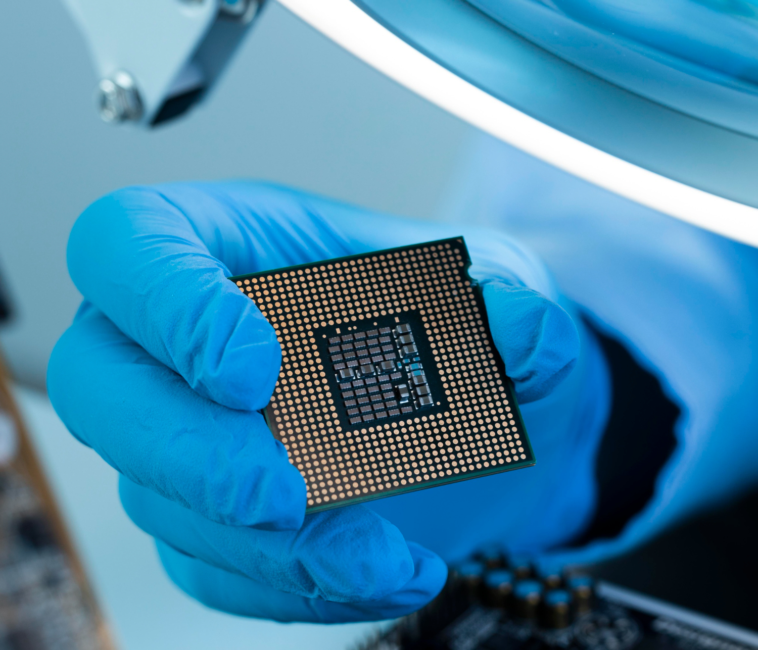
High-yield assembly isn’t about luck or expensive equipment — it’s about the decisions made long before a board reaches production. From pad design to stencil choices, stack-up communication to test-point planning, many of the biggest yield influencers sit directly in the hands of designers and hardware teams.
This guide breaks down the most common high-yield PCB assembly challenges and shows how simple, intentional design choices prevent defects before they start. Where the process goes beyond design, we also explain how the right assembly partner — one built on control, visibility, and disciplined process — keeps your builds predictable and rework-free.
Design choices that protect high-yield PCB assembly
A high-yield build starts at the drawing board, not at the assembly line. Clean component libraries, consistent land patterns, and realistic courtyards remove ambiguity for both engineers and machines. Clear polarity markings and visible pin-1 indicators prevent orientation mistakes during placement.
- Ensure escape routing avoids solder mask slivers
- Add test points early so you don’t cut traces later
- Share your stack-up, copper weights, surface finish, and critical tolerances with your assembler before freezing the design
Early collaboration between design and assembly prevents issues from surfacing on the line — where they’re far more expensive to fix.
Paste print: The first gate
Most downstream defects trace back to issues in stencil printing. You can’t operate the printer, but you can influence print quality through your documentation and stencil choices. Choose a stencil thickness that matches your component mix, specify aperture reductions correctly, and confirm solder paste shelf life and storage compliance at the start of each build.
Tombstoning: why it happens and how to fix it
Tombstoning occurs when a passive component lifts from one pad during reflow — one of the most common yield problems, and one of the most avoidable.
- Optimised pad design with balanced pad sizing
- Precise thermal relief patterns so solder wets evenly on both pads
These design and patterning adjustments ensure equal heat distribution, preventing one pad from melting faster than the other and pulling the component upright.
Solder bridging: preventing shorts before they start
Solder bridging often appears between fine-pitch leads. While print settings matter, several design-side controls help minimise it:
- Use aperture reductions in dense areas
- Maintain proper solder mask webbing
- Validate paste volume assumptions during DFM review
AOI catches remaining defects, but good stencil and mask design keeps bridging minimal from the outset.
Component misalignment: Small shift, big impact
Component misalignment usually comes down to pick-and-place vision alignment and fiducial quality — both areas where designers have real influence.
- Add global and local fiducials with correct clearances
- Avoid placing critical components near board edges or panel break-offs
- Ensure accurate XY data in the centroid file
Combined with AOI and X-ray inspection at your PCB assembler, these steps significantly reduce positional drift.
Reflow profiles that forgive variation
A strong reflow profile gives every solder joint a fair, consistent chance to form correctly. Reflow profiling is your assembler’s responsibility, but designers heavily influence how forgiving that profile can be.
| Design Factor | Yield Impact |
|---|---|
| Copper imbalance across board | Uneven heat absorption, inconsistent reflow |
| Surface finish vs. pitch/thermal demand | Wetting quality, void formation |
| High-mass component grouping | Profiling consistency, fewer opens |
Make yield a habit, not a hope
High yield becomes predictable when designers take control of what they influence: clean data, good pad design, stable mask geometry, correct solder volume, accessible test points, and balanced layouts. Capture these practices in your internal checklists and apply them consistently from prototype to production.
Why Alica Technologies is the right partner for high-yield PCB assembly builds
High yield doesn’t come from inspection alone — it comes from a partner who engineers reliability at every stage. At Alica Technologies, AOI, X-ray, and rigorous SPI checks are backed by disciplined process control: precise paste-print control, validated placement and part data, and reflow profiles tuned to your actual stack-up and board mass.
This combination of diagnostics and disciplined process gives you cleaner first articles, fewer re-spins, and a far more predictable production ramp.
For a deeper look at our inspection process, see our guide on AOI and X-ray testing, or read how we approach SMT and THT assembly.
Get a Quote for Your Next High-Yield Build | Call us: +91 97271 78787
Frequently Asked Questions
What should designers review first to improve yield?
Start with solder paste-related decisions: stencil thickness, aperture reductions, paste specification, and SPI limits.
When should reflow profiles be re-validated?
Whenever you change solder paste, copper density, board mass, or high-power components.
Are no-clean builds truly “no clean”?
Not always. If residues affect high-voltage nodes or coating adhesion, request cleaning verification such as ROSE or SIR testing.
What designer-side training improves results fastest?
Short, visual checklists for stencil design, pad geometry, test-point planning, polarity markings, and fiducial best practices.
How can designers prevent repeat defects?
Share fixes back into ECAD libraries and maintain a rolling defect log with before/after photos.