
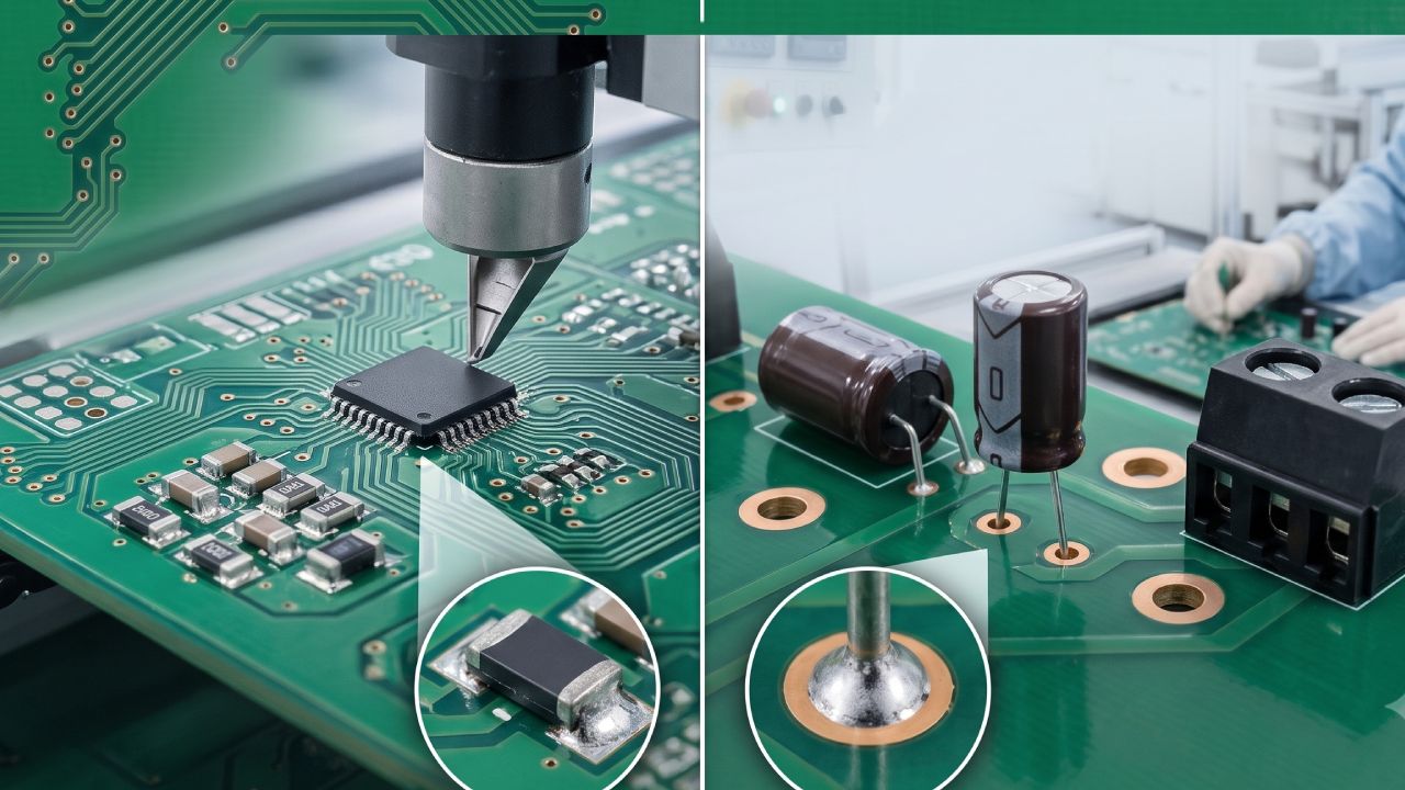

For product engineers designing a new electronic assembly, one of the earliest and most consequential decisions is the choice of component packaging and assembly technology: SMT (Surface Mount Technology), THT (Through-Hole Technology), or a mixed approach combining both.
This choice cascades into everything downstream — PCB design rules, component sourcing, EMS partner selection, assembly cost, testing methodology, and long-term reliability. Choose incorrectly, and you may end up with a design that costs 40% more to assemble than it needs to, or worse — one that fails in the field because a mechanically stressed component was mounted using the wrong process.
This guide breaks down the SMT vs THT question in the depth a working product engineer or procurement lead actually needs: what each technology is, where each excels, where each fails, and how to structure a mixed-technology approach when your product needs both.
What is SMT (Surface Mount Technology)?
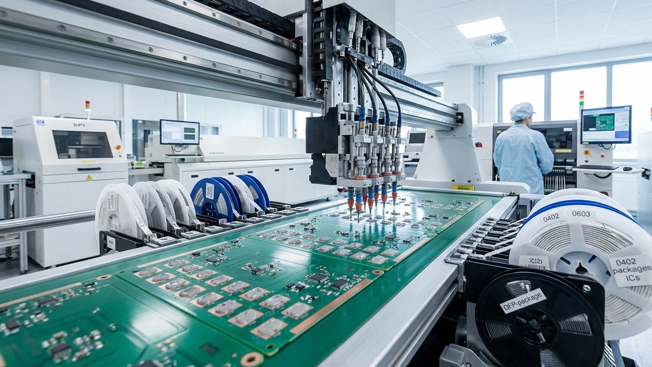 Surface Mount Technology (SMT) is a PCB assembly process where electronic components are placed directly onto pads on the surface of the printed circuit board and soldered in place using a reflow oven. There are no leads passing through the board — the component sits on top of the copper pads, held by solder joints formed from paste deposited before placement.
The SMT Process — Step by Step
- Solder Paste Printing: A stencil is aligned over the PCB, and solder paste (a mixture of solder alloy powder and flux) is squeegeed through apertures onto the pads.
- Solder Paste Inspection (SPI): An SPI machine measures the volume, height, and position of each paste deposit before component placement.
- Component Placement: Pick-and-place machines with vacuum nozzles retrieve components from feeders and place them on the paste deposits with micron-level accuracy.
- Reflow Soldering: The board passes through a reflow oven with a carefully engineered thermal profile — preheat, soak, peak, cooling — melting the solder paste and forming permanent joints.
- Post-Reflow AOI: Automated Optical Inspection verifies component presence, polarity, and solder joint quality.
- X-Ray Inspection: For hidden joints under BGA, QFN, or LGA packages, X-ray inspection verifies solder integrity.
Typical SMT Component Packages
- Passives: 0201, 0402, 0603, 0805, 1206 chip resistors and capacitors
- ICs: SOIC, QFP, QFN, BGA, LGA, WLCSP
- Discrete semiconductors: SOT-23, SOT-223, DPAK, D2PAK
- Fine-pitch devices: Down to 0.3mm pitch on high-density boards
What Is THT (Through-Hole Technology)?
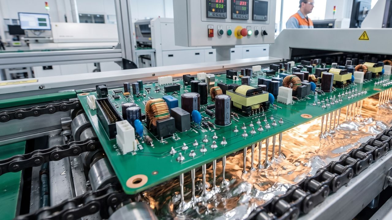 Through-Hole Technology (THT), sometimes called PTH (Plated Through-Hole), is the older PCB assembly method where components have wire leads that pass through drilled holes in the board and are soldered on the opposite side. The mechanical anchoring created by the through-hole connection makes THT joints significantly stronger than surface-mount joints.
The THT Process — Step by Step
- Component Insertion: Leads are inserted through drilled and plated holes, either manually by an operator or automatically by axial/radial insertion machines.
- Lead Trimming and Clinching: Leads on the underside are trimmed to length and often bent (clinched) to hold the component before soldering.
- Soldering — Wave or Selective:
- Wave Soldering: The board passes over a wave of molten solder, coating all exposed leads simultaneously. High throughput but not suitable for mixed boards with sensitive SMT components on the underside.
- Selective Soldering: A programmable nozzle applies solder to specific joints only, allowing THT components on the same board as sensitive SMT assemblies.
- Hand Soldering: For very low volumes, sensitive components, or rework, joints are soldered manually by trained operators.
- Post-Solder Inspection: Visual inspection and, where required, X-ray verification of solder fill within the plated through-hole.
Typical THT Component Packages
- Electrolytic capacitors (large radial and axial types)
- Transformers and inductors (heavier magnetics)
- Power connectors and terminal blocks
- Relays and mechanical switches
- DIP-package ICs (increasingly rare in modern designs)
- High-current power components
SMT vs THT: Head-to-Head Comparison
The table below summarises the core differences engineers should weigh when choosing between the two assembly technologies:
| Parameter | SMT | THT |
|---|---|---|
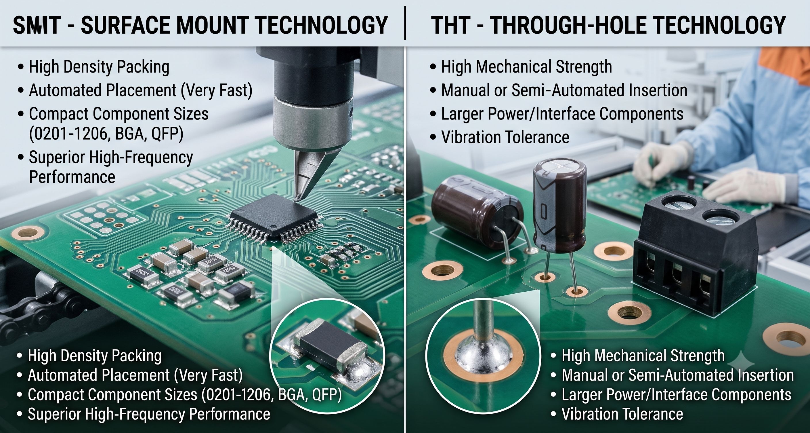
| Component Size | Extremely small (down to 0201, 01005) | Larger footprint required |
| Board Density | Very high — both sides can be populated | Lower — leads occupy space on both sides |
| Assembly Speed | Very high (10,000–50,000+ components/hour) | Slower — insertion is more mechanical |
| Automation Level | Fully automated end-to-end | Partially automated, often needs manual handling |
| Mechanical Strength | Lower — solder joints only | Higher — mechanical anchoring through the board |
| Cost per Joint | Lower at scale | Higher due to process time |
| Setup Cost | Higher — stencils, feeders, programs | Lower — but scales poorly with volume |
| Rework Difficulty | Harder — requires hot air, BGA rework stations | Easier — desolder, replace, resolder |
| Vibration Tolerance | Lower — joints are the only anchor | Higher — mechanical support from board |
| High-Frequency Performance | Superior — shorter lead lengths, less parasitic inductance | Weaker — longer leads add inductance |
| Thermal Handling | Sensitive to reflow profile | Handles higher power components better |
When to Choose SMT
Surface Mount Technology is the correct choice when your product requires any combination of the following characteristics:
High Component Density
If your board needs to fit hundreds of components in a small area — modern smartphones, IoT devices, wearables, industrial sensors — SMT is the only viable path. SMT allows components on both sides of the PCB and supports the smallest available package sizes.
High Volume Production
SMT lines run at throughput rates that make THT uneconomical at scale. Once the SMT program is set up and validated, per-unit assembly cost is minimal, making SMT the default choice for any product with anticipated volumes above a few thousand units per year.
High-Frequency or RF Circuits
The shorter effective lead length of SMT components introduces less parasitic inductance and capacitance, making SMT essential for RF, high-speed digital, and analog signal chains operating above a few hundred MHz.
Fully Automated Testing Downstream
SMT-only assemblies are well-suited to inline testing with AOI, X-ray, ICT, and Flying Probe systems — enabling consistent throughput and traceability across the entire production line.
When to Choose THT
Through-Hole Technology remains the correct choice for a specific set of scenarios:
High Mechanical Stress Environments
Products subjected to significant vibration, shock, or physical handling — connectors that will be plugged and unplugged thousands of times, power terminals, industrial equipment on factory floors — benefit from the mechanical anchoring that only THT provides.
High-Current or High-Voltage Components
Large electrolytic capacitors, transformers, high-current inductors, and power relays generate mechanical stress from their own mass and heat. Surface-mount versions of these components exist but often can’t match the current-carrying capacity or thermal dissipation of THT equivalents.
Prototyping and Very Low Volumes
For prototype builds of 5–20 units, or hand-assembled products where SMT tooling costs cannot be justified, THT remains practical because it can be assembled without automated pick-and-place equipment.
Legacy Product Support
Products designed 15+ years ago frequently rely on THT components that remain in production. Re-designing to SMT equivalents introduces cost, validation effort, and risk that may not be justified for a mature product.
Mixed Technology: The Reality of Modern PCB Assembly
The vast majority of industrial, automotive, medical, and telecommunications PCBs in production today are mixed-technology assemblies — SMT components for the bulk of the design, THT for high-stress connectors, power components, and mechanically demanding parts.
Mixed-technology assembly is more complex than either pure SMT or pure THT because it requires managing the thermal budget of the board across multiple soldering processes. A typical mixed-technology process flow looks like this:
- Top-side SMT: Solder paste print, place, and reflow all top-side surface-mount components.
- Bottom-side SMT (if applicable): Second paste print, place, and reflow for bottom-side components. Adhesive may be used to hold components during reflow.
- THT Insertion: Manual or automated insertion of through-hole components.
- Selective Soldering: A selective soldering machine solders THT joints without exposing SMT components to a second full-board thermal cycle.
- Final Inspection and Test: AOI, X-ray, ICT, or functional test as required by the product specification.
Choosing an EMS partner with capability across all three processes — top-side SMT, bottom-side SMT, and selective THT — eliminates the risk of sub-contracting or splitting production across multiple vendors.
For a deeper look at what to evaluate in an assembly partner, see our detailed guide on choosing a PCB assembly partner in Ahmedabad.
Cost Analysis: SMT vs THT at Different Volumes
 Assembly cost differs significantly between SMT and THT, and the differential shifts with volume:
Prototype Volume (1–50 units)
At prototype volume, THT can actually be cheaper per unit because SMT setup costs — stencil fabrication, feeder loading, machine programming — are amortised across only a handful of boards. Many EMS providers offer prototype pricing that reflects this reality.
Low Volume (50–1,000 units)
At low volume, SMT and THT costs converge. The SMT setup investment begins to pay off, but per-unit assembly time is still a meaningful factor.
Medium to High Volume (1,000+ units)
At medium and high volume, SMT is dramatically cheaper per component placed. A modern SMT line places 10,000–50,000+ components per hour with minimal operator involvement. THT insertion — even with axial and radial insertion machines — cannot match this throughput.
Reliability Considerations: Which Lasts Longer?
Reliability comparisons between SMT and THT are more nuanced than a simple “which is more reliable” question suggests. The correct framing is: reliable under what stress conditions?
- Thermal cycling: SMT solder joints — particularly on BGA packages — are more susceptible to fatigue cracking under repeated thermal cycling because there’s no mechanical anchor to absorb differential expansion between component and board.
- Mechanical shock and vibration: THT wins decisively. The through-hole barrel provides mechanical support that no solder-only joint can match.
- Long-term storage: Both technologies are comparable if stored under controlled conditions.
- Humidity and corrosion: Comparable, provided post-assembly cleaning is properly performed on both.
For life-critical applications — aerospace, defence, medical — the IPC-A-610 Class 3 standard applies to both SMT and THT joints and defines acceptance criteria for each.
Design Implications: How SMT vs THT Affects PCB Layout
The choice of SMT vs THT affects PCB design in several practical ways:
- Board Real Estate: SMT allows components on both sides of the board; THT effectively consumes both sides for a single component due to the through-hole footprint.
- Layer Count: SMT dense designs often require more PCB layers for routing; THT designs sometimes get away with fewer layers due to lower density.
- Via Placement: THT holes act as vias between layers, sometimes simplifying routing. SMT designs need separate via placement.
- DFM Rules: SMT introduces stringent stencil aperture ratio requirements, component clearance rules, thermal balance considerations for small passives, and BGA escape routing constraints that don’t apply to THT-heavy boards.
- Testpoint Strategy: Test point placement differs — SMT boards often rely on dedicated test pads, while THT boards can sometimes probe existing component leads.
How Alica Technologies Handles SMT, THT, and Mixed Technology
At Alica Technologies, our PCB assembly facility in Ahmedabad is equipped for full SMT, THT, and mixed-technology production under one roof:
- Automated SMT lines with SPI, high-accuracy pick-and-place, and inline AOI
- 2D X-ray inspection for BGA, QFN, and hidden solder joint verification
- Selective soldering capability for mixed-technology boards where wave soldering would damage SMT components
- Manual soldering stations staffed by IPC-A-610 trained operators for prototype builds and rework
- IPC-recommended SOPs applied consistently across all three assembly technologies
Whether your product is pure SMT, pure THT, or (most commonly) a mixed-technology assembly, we scope the process flow to your specific board — not to a fixed line configuration that forces compromises.
Frequently Asked Questions
What’s the main difference between SMT and THT?
The core difference is how components are attached to the PCB. In SMT, components sit on the surface of the board and are soldered to pads. In THT, component leads pass through drilled holes in the board and are soldered on the opposite side, creating a mechanical anchor as well as an electrical connection.
Is SMT cheaper than THT?
At medium and high production volumes, SMT is significantly cheaper per component because of automation and throughput. At prototype and very low volumes, THT can actually be cheaper because SMT setup costs (stencils, feeders, programming) are difficult to amortise over a small number of boards.
Can SMT and THT be used on the same PCB?
Yes — and in fact, most modern industrial and commercial PCBs are mixed-technology assemblies. SMT is used for the bulk of the design, with THT reserved for connectors, power components, transformers, and mechanically stressed parts. The assembly process uses selective soldering for the THT components to avoid subjecting SMT parts to a second full reflow cycle.
Is SMT more reliable than THT?
It depends on the stress condition. THT is more reliable under mechanical shock and vibration because of the through-hole anchoring. SMT can be equally or more reliable in benign environments, but SMT joints — particularly BGA — are more susceptible to thermal cycling fatigue over long periods.
Which is better for high-volume production?
SMT is dramatically better for high-volume production. Modern SMT lines place tens of thousands of components per hour with minimal operator involvement, while THT insertion is fundamentally slower even with automated equipment.
What components can only be assembled using THT?
Large electrolytic capacitors, transformers with heavy magnetics, high-current connectors, industrial relays, terminal blocks, and certain high-power discrete semiconductors are typically only available in THT packages or perform meaningfully better in THT form.
Do I need different EMS partners for SMT and THT?
No — a fully capable EMS partner should offer SMT, THT, and mixed-technology assembly under one roof, along with selective soldering for mixed boards. Splitting production between vendors introduces logistics risk, quality accountability gaps, and cost inefficiency.
How does IPC classify SMT vs THT quality?
IPC-A-610 (Acceptability of Electronic Assemblies) defines acceptance criteria for both SMT and THT joints across three quality classes: Class 1 (general electronics), Class 2 (dedicated service), and Class 3 (high reliability). The class determines the strictness of the inspection criteria — not the technology used.
Is THT technology becoming obsolete?
No. While SMT dominates in modern designs, THT remains essential for mechanically stressed components, high-power parts, and legacy product support. Most PCBs in production today use both technologies together.
What’s the minimum component size for SMT?
Modern high-end SMT lines can place components as small as 01005 (0.4mm × 0.2mm) and fine-pitch ICs down to 0.3mm pitch. Most mainstream production uses 0201 or 0402 as the smallest passive, with fine-pitch ICs at 0.4mm–0.5mm pitch.
Conclusion: Choose the Technology Your Product Actually Needs
The SMT vs THT decision is not a technology preference — it is a set of engineering trade-offs specific to your product’s density, volume, environment, and cost targets. The right approach for most modern products is a considered mix: SMT for density and cost efficiency, THT for mechanical strength and high-power components, and selective soldering to bring them together on one board without compromising either.
The right EMS partner should have all three capabilities under one roof, and should engage with your design at the DFM stage — not just at the assembly stage — to help you make the right technology choice for each component group on your board.
If you’re evaluating an EMS partner for a mixed-technology product, we’d welcome a technical conversation about your assembly requirements.
Get a Quote | View Our Services | Call us: +91 97271 78787
Alica Technologies LLP is an Electronics Manufacturing Services (EMS) company based in Ahmedabad, Gujarat, specialising in SMT, THT, and mixed-technology PCB assembly, AOI & X-ray inspection, and turnkey electronic manufacturing for OEMs across India.